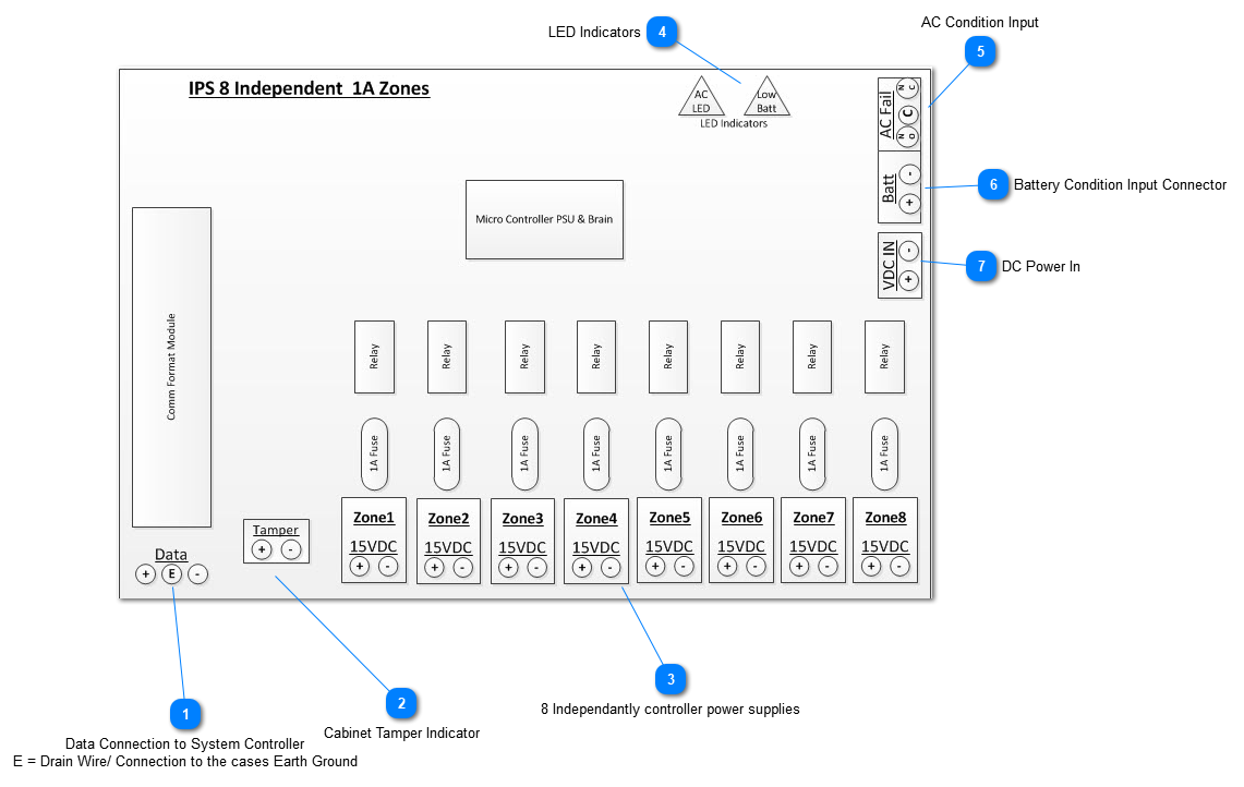
Board Diagram - IPS 8 Zone PCB
 Data Connection to System Controller
E = Drain Wire/ Connection to the cases Earth Ground |
|
 Cabinet Tamper Indicator
|
|
 8 Independantly controller power supplies
|
|
 LED Indicators2 LED Indicators show in AC (green) DC (Red) and status of backup battery - Green - good, Red Low Battery
|
|
 AC Condition Input
|
|
 Battery Condition Input Connector
|
|
 DC Power In
|
|