Converting an Axcys Modem Keypad to RS485
IMPORTANT! -
Take pictures of the inside of the keypads BEFORE you disassemble any of it.
Take pictures of the Communicator wiring BEFORE unplugging it.
Take pictures of ALL power supplies BEFORE disconnecting them.
WARNING!
Never plug in, unplug, remove PCB modules when the unit is powered on. You may unplug only the power connector while power is turned on.
WARNING!-
DO NOT REMOVE WIRES FROM THE 4 PIN POWER or 3 PIN DATA CONNECTOR!
It is NOT necessary to remove the wires from the 4 pin Power & Data Connector. Doing so may complicate the conversion since Global has NO WAY TO KNOW WHAT EACH COLOR WIRE MEANS IN YOUR APPLICATION!
NOTE A. Review the section "How to Replace Component Modules" here
NOTE B. RS485 is polarized like a battery with Plus (+) and Minus (-) wires. Modem is NOT polarized. If after replacing the modules in the kepads and the Communicator, the installer needs to verify that the POLARITY is correct. Check the data wires in the pictures of each keypad to be sure they are all the same.
See Here for a wiring diagram
Step 1. Power off all Keypads and Communicator
Step 2. Remove Face Plates of Keypads from their rear enclosures.
Step 3. Remove the top of the Communicator, taking care to HOLD the front and rear panels with your hand/finger, to avoid breaking the LED's in the front.
Step 4. Remove the Comm Format Module from each keypad and Communicator
Step 5. Insert (replace the Modem Module) with the RS485 Comm Format Module in each Keypad and Communicator.
**Be sure to that each end of the module is plugged in completely - See here
Step 6. Power on all devices
Step 7. Use DiagnostyX to check functional polling on the Axcys or DiagnostyX screen. If not polling correctly there is either a setup problem in Axcys (needs to be changed from Modem to Axcys485) or a wire polarity problem. Refer to NOTE B.
Step 7a. If polarity is an issue AND you are using a phone jack/cord at the Communicator, the easiest place to make the change is at EACH keypad. Swap the data wires on the 4 PIN connector (pins 3 and 4). You should see the middle (RXD) LED on the Keypad Main Board light periodically as well as the Left LED (TXD) light periodically.
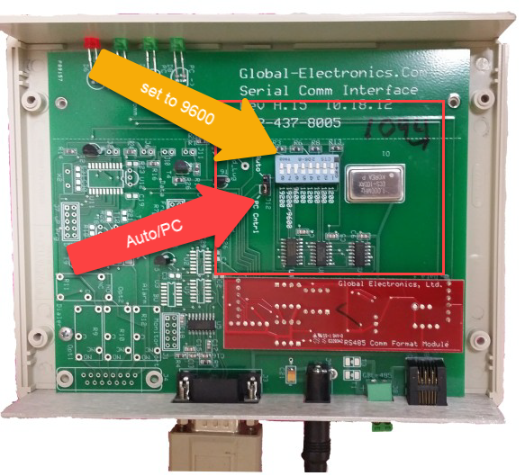
Step 8. Move the jumper from the Center and Bottom Pins (in the photo below) to the Center and Top Pins changing the setting to "Auto"
Step 9. Verify that the two slide switches where 9600 are shown are set to ON.
Note that if your model of Communicator does not have the settings below, it will probably still work. *However* the polarity of the data wires are backward from these newer models. So if you have one of each, you will probably want to trade in the older model for a newer, if you want a spare Communicator.