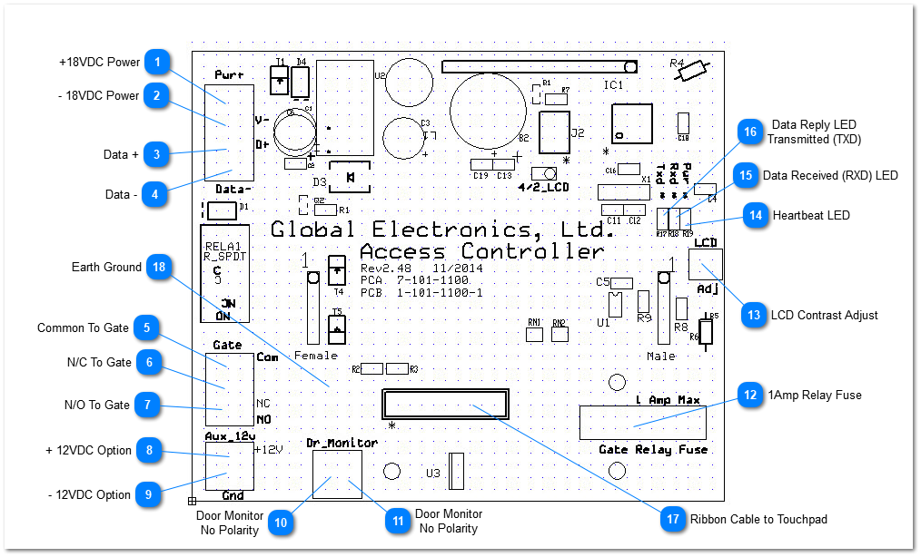
Power cable and Data cable should be 18AWG Stranded shielded with a drain wire. The Drain wire should be attached ONLY to the Ground Lug inside the rear of the case.
Power cable and Data cable should be 18AWG Stranded shielded with a drain wire. The Drain wire should be attached ONLY to the Ground Lug inside the rear of the case.
Power cable and Data cable should be 18AWG Stranded shielded with a drain wire. The Drain wire should be attached ONLY to the Ground Lug inside the rear of the case.
Power cable and Data cable should be 18AWG Stranded shielded with a drain wire. The Drain wire should be attached ONLY to the Ground Lug inside the rear of the case.
EclypX keypads are shipped with the LCD adjusted for best contrast. This however can change due to temperature and humidity changes. To adjust this setting, using a small screwdriver turn first one way, then the other to find the optimum setting.
This Light Emitting Diode (LED) blinks periodically or may stay on depending on the model and version of board you have. It is a simple indicator that the micro-controller 'brain' is working.
This LED blinks whenever data is received by the device. It will go on whether the data is intended for this device or any other device so long as the data is of the correct form.
This LED blinks whenever data is Transmitted by the device to the System Controller. It only blinks when the device is replying to a message from the System Controller Software
Global normally provides a green ground cable with ring terminals from this point. The other end of the ground wire should be attached to the ground lug inside the rear of the case. See grounding for more details and warnings concerning proper grounding.